Shaft (Coupling) Alignment
Precision laser alignment with 0.01 mm resolution
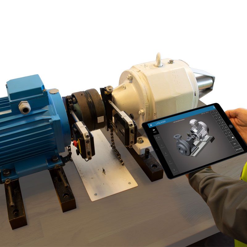
We align coupled machine trains such as motor-pump and motor-gearbox sets with a laser system. Soft-foot checking, thermal growth compensation and precut shims deliver a lasting result.
- Laser horizontal and vertical alignment, 0.01 mm resolution
- Soft-foot measurement and correction
- Thermal growth compensation
- Lasting correction with stainless precut shims
- Pipe strain checking
- Before/after report documenting tolerance
Why misalignment matters
Misalignment is one of the most common causes of bearing and seal failure in industry. Even with a flexible coupling, misalignment creates a cyclic load on the shaft that shortens bearing life, wears the seal, fatigues the coupling element and increases energy consumption.
Traditional alignment with a straight edge and dial indicator typically stays around 0.1 mm. A laser system measures to 0.01 mm resolution and gives correction values directly per foot.
Process
- Pre-checks. Foundation bolts, shim condition, coupling wear and pipe strain are checked.
- Soft-foot measurement. Each of the four feet is loosened in turn to measure and correct the planarity error. Alignment carried out without correcting soft foot does not last.
- Laser measurement. LineLazer sensors are mounted on the shafts; thanks to the modulated line laser and precision inclinometers, measurement completes with less than half a turn of the shaft.
- Thermal growth compensation. The change in height at operating temperature is taken into account.
- Correction. Vertical correction with precut stainless shims, horizontal correction with jacking bolts.
- Verification and reporting. The final state is measured and documented as within tolerance.
Tolerance
Alignment tolerance depends on speed: the higher the speed, the tighter the tolerance. In practice a typical acceptance limit at 1500 rpm is 0.07 mm offset / 0.07 mm per 100 mm angular, and around 0.05 mm at 3000 rpm. Where the machine manufacturer specifies a figure, that governs.
Frequently asked questions
What is the difference between laser alignment and the dial indicator method?
With dial indicators, accuracy is affected by bracket sag and reading error; in practice it yields results around 0.05–0.1 mm and correction values must be calculated by hand. A laser system has no sag, measures to 0.01 mm resolution, and displays the correction directly for each foot. Because less than half a turn of the shaft is enough, it is also possible to work in confined spaces without removing the coupling. The time difference is significant too: a typical motor-pump set that takes close to half a day with dial indicators is usually completed in under an hour with laser.